
JCT software user documentation
Instructions for using the JCT software for running experiments, including descriptions of input and output file formats
Version 2.2
Joseph Eddy, 10
August 2005
Based upon original version 1.0
by Tim Taylor, 20 May 2005
Last update: Craig Nicol, 22 November 2005
Introduction
This document describes the configuration and use of the JAST Joint Action software and the format of the output data file.
Virtually every aspect of an experiment's behaviour and appearance can be easily specified in the configuration file passed to the program at start up.
When the program begins, it requests a configuration file. This is an experiment configuration file (an xml file of doctype JastExpt), the format of which is explained below. This JastExpt file specifies general details of the experiment, such as the names of the two computers, the text to be shown to the subjects in various situations, the appearance of the cursors, the time limit for the trials, etc.
At the end of the JastExpt file is a list of StimulusSet files. The StimulusSet files provide details of an individual trial; they define the set of shapes used in the trial, their initial layout on the screen and their target configuration.
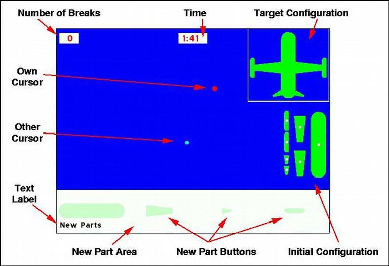
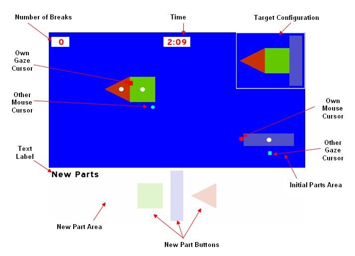
For reference in the following sections, the main components on the experiment as they appear on screen are indicated in the following figures.
General Interaction with the Software during an Experiment
When the program starts, it displays a message to say it is waiting for a connection from the other machine. When this message is displayed on both machines, click OK on both machines, and the connection is made. The experimenter is also asked to supply the name of a data file into which data will be recorded during the experiment. If the eye-tracker version of the program is being used, the software will go into eye-tracker configuration mode, in which the experimenter may set up and adjust the eye tracking cameras, and do calibration and validation of the calibration. To leave eye-tracker configuration mode, click the “Offline” button on the eye-tracker host machine. At the beginning of each trial in the eye-tracker version of the program, a screen will be displayed with a fixation point in the centre, this is for drift correction, and the experimenter should accept the fixation once the user fixates on the point. It is easiest if drift correction fixation is accepted on the client machine first (see description of ServerPC and ClientPC in the section "Experiment Configuration Files" for an explanation of the distinction between client and server machine), so the subject on the server machine can’t accidentally start the trial before the client subject is ready. Once these setup actions have been performed, the screen is initialised and a message appears asking the subject to prepare for the beginning of the trial (on the client machine), or to press any key to start the trial (on the server machine). At the start and end of each trial, a synchronisation signal is played consisting of an asterisk at the top of the screen, a beep from the internal speaker and the Windows "Asterisk" sound played once.
The subjects interact with the parts by left-clicking on a part to drag it, and right-clicking to rotate it. Parts rotate about a point of rotation indicated by a small circular graphic (the white dots on the parts in the figures above). Parts can be joined if both subjects drag a part each and they come into contact. Parts break if both users attempt to drag and/or rotate the same part at the same time. Parts also break if they are dragged into the New Part Area (specifically, if the point-of-rotation graphic on the part enters the New Part Area). When a part has been broken, a replacement part can be obtained by clicking on the appropriate New Part Button. The user must left-click on the button and keep the left button pressed while dragging the new part into the main working area of the screen. While this is happening, the new part is shown semi-transparent. The part only actually becomes a fully-functioning part when it is released (the user releases the left mouse button) in the working area (at which point the new part becomes fully opaque). If a new part collides with another part while it is still semi-transparent, or if it is released while still in the New Part Area, it is removed (although not counted as a break).
If a time limit has been specified for the trials (see below), the trial will end when the limit is reached, and the subjects will score zero for that trial if they have not already stopped the trial.
When a subject thinks that the model is complete, they should press the SPACE BAR on the keyboard. They then get a message to say that they should wait for the other subject to respond. The first subject cannot interact with the trial any further until the other subject has responded. The other subject gets a message to say the first subject has requested that the trial ends. The second subject should then press the Y key if they are happy for the trial to end, or the N key if they think the model is not ready. If they press Y, the trial end, both subjects are shown the score they achieved (if it is specified in the config file that this should happen), and the software prepares for the next trial (if any remain). If they press N, the messages on both subjects' screens disappear, and the trial continues (both subjects can interact with the trial again).
At any stage during a trial, the experimenter can press the ESC key to break out of the experiment immediately (stopping the current trial and any ones still to be run).
Experiment Configuration Files (doctype JastExpt)
In the JAST distribution, four example JastExpt files are provided: ExampleJastExpt.xml, AeroplaneJastExpt.xml, ExampleJastExptBothCursors.xml, and AeroplaneJastExptBothCursors.xml. Look at these to get a general feel for what the JastExpt files contain. Most of the content of these files should be self-explanatory.
The individual elements available in the JastExpt file are as follows, and must be included in the order they are listed here. Recognised children of each element in the file are denoted by indentation of the header name. The structure here is also defined in the JastExpt.dtd file included in the JAST distribution.
Title
Provides a title for the configuration file. At present this title is not actually used in the software, although it does appear in the output data file.
ServerPC
Gives the name of the PC that will act as the server in the experiment. This machine keeps a definitive version of the state of the experiment at any instant. The Server PC is also responsible for recording data.
When the program runs, the software queries the PC on which it is running to request the PC's name. If this name matches the name specified in "ServerPC" then the PC adopts the role of Server. A message then appears to inform the user that the server is waiting for a connection from the client machine (unless the client is running in simulate="true" mode - see below).
HINT: this message contains the local PC's name, in square brackets; if you are not sure what names to use in ServerPC and ClientPC, look at the name that comes up in this message when the program begins.
ATTRIBUTES: timeout: time (in seconds) the server will wait for a connection from the ClientPC. If no connection is made in this time, the program quits.
ClientPC
Gives the name of the PC that will act as the client.
ATTRIBUTES: simulate (true|false): if true, the software runs on a single machine (in which parts join together when one is dragged into another even if no-one is holding the other part). This is mainly for testing purposes. Ordinarily simulate should be set to false.
Colours
This section defines a list of colours which can then be referred to in the rest of the file.
Colour
Defines a colour from specified Red, Green, Blue values, and gives it a name
ATTRIBUTES: name, r, g, b: name is any text. r, g, and b are numeric values between 0 and 255 to specify levels of red, green and blue.
NOTE: Because of an oddity in the way the graphics are implemented, you should not use a colour with RGB values of 0,0,0, as this may have unpredictable results (technically, 0,0,0 is used as the transparent "colour key"). If you want to define a colour black, you should use a different value, e.g. 1,1,1.
Display
Defines some general characteristics of the display
ATTRIBUTES: width, height: the resolution of the display (NOTE, this should be a resolution supported by your display and graphics card). fullscreen (true|false) if true, the software goes into fullscreen mode during trials; if false, the trial appears in a window (this should normally only be used for testing). colour: defines the background colour of the display. synccolour: defines the colour of the visual sync signal; this should be set to something with good contrast against colour.
Font
Specifies the name of a TrueType font to be used for displaying text on screen. A default font file, named font.ttf, is supplied, but other font files could be used if desired.
ATTRIBUTES: size, colour: specify the default font size and colour.
CursorOwn
Defines the appearance of the subject's own cursor on their screen.
ATTRIBUTES: diameter: the size of the cursor. colour: the normal colour. colourDrag: the colour of the cursor when the subject is dragging a part. colourRotate: the colour of the cursor when the subject is rotating a part.
CursorOther
Defines the appearance of the subject B's cursor on subject A's screen.
ATTRIBUTES: diameter: the size of the cursor. colour: the normal colour. colourDrag: the colour of the cursor when subject B is dragging a part. colourRotate: the colour of the cursor when subject B is rotating a part.
EyeCursorOwn
Defines the appearance of the subject's own eye-gaze cursor on their screen. This element only has an effect when using the eye-tracker version of the program. It is optional, as well: if it is left unspecified, then the subject’s own eye-gaze will not be tracked by a cursor on her screen.
ATTRIBUTES: diameter: the size of the cursor. colour: the colour of the cursor.
EyeCursorOther
Defines the appearance of the subject B's eye-gaze cursor on subject A's screen. This element only has an effect when using the eye-tracker version of the program. It is optional, as well: if it is left unspecified, then subject B’s eye-gaze will not be tracked by a cursor on subject A’s screen.
ATTRIBUTES: diameter: the size of the cursor. colour: the colour of the cursor.
TargetConfigBox
Defines the appearance of the Target Configuration Box
ATTRIBUTES: drawborder (true|false): if true, a border is drawn around the box (of width "linewidth", colour "colour"). shadebackground (true|false): if true, the whole box area is drawn in colour "colour".
NewPartBox
Defines the appearance of the New Part Area Box
ATTRIBUTES: drawborder (true|false): if true, a border is drawn around the box (of width "linewidth", colour "colour"). shadebackground (true|false): if true, the whole box area is drawn in colour "colour". indicatePartAvailable (true|false): if true, the individual part buttons are drawn opaque if the user can create a new part of that type at that time, otherwise it is drawn semi-transparent to indicate that new parts of that type are currently unavailable. If indicatePartAvailable is set to false, part buttons are always opaque, so the subjects get no hint as to whether a part is available or not.
PartOptions
Defines the appearance and behaviour of movable parts on screen.
ATTRIBUTES: rotatable (true|false): if false, parts cannot be rotated (NOTE: this is not implemented at present: parts can always be rotated, regardless of the option specified here). hsSize: defines the size of the "Hot Spot" graphics that represents the point of rotation of a part. The precise interpretation of hsSize depends upon the value of hsAsPercentage (true|false); if true, hsSize is interpretted as a percentage of the part's total area (e.g. is hsSize=20, the area of the Hot Spot graphic will be 20% of the area of the part - with a minimum diameter specified by hsMinSize, expressed in number of pixels). if hsAsPercentage is false, hsSize is interpretted as an absolute diameter (in pixels) that will be used for Hot Spot graphics on any part. The Hot Spot graphic is drawn in colour "colour".
Score
Defines aspects of the scoring of a model when the subjects complete the task, and whether the score is displayed to the subjects.
ATTRIBUTES: display (true|false): if true, the score is shown on screen to both subjects when they have completed the trial. If false, and end of trial message (see "NoScoreMessage") is shown instead. displayDuration: defines how long (in seconds) the score is displayed on screen. scoreIncompleteModels (true|false): if true, the software attempts to give a score to a model even if it is incomplete (i.e. has parts missing). NOTE: there a various tricky issues involved in scoring incomplete models, and the current implementation is not perfect. It is much safer to stick to "false" for this option, in which case all incomplete models get a score of zero.
Time
Defines whether a time limit is put on trials, and the appearance of the clock on the screen.
ATTRIBUTES: limit: defines the time limit to each trial (in seconds). limit=0 means no time limit. display (true|false): if true, a clock is shown on screen to show how much time remains. direction (up|down) if up, the clock counts up from zero, if down, it counts down from the time limit. size: defines the font size in which the clock is displayed. style (normal|bold|italic|underline): defines the font style for the clock. x: defines the x position at which the clock is drawn on screen (if x=-1, the clock is positioned half-way across the screen). y defines the y position at which the clock is drawn. fgColour defines the foreground colour of the clock text. bgColour defines the colour of the box on which the clock text is written.
Cost
Defines whether a count of number of broken parts is displayed, and its appearance on the screen.
ATTRIBUTES: display (true|false): if true, a count is shown on screen to show the number of broken parts. size: defines the font size in which the count is displayed. style (normal|bold|italic|underline): defines the font style for the count. x: defines the x position at which the count is drawn on screen (if x=-1, the clock is positioned half-way across the screen). y defines the y position at which the count is drawn. fgColour defines the foreground colour of the count text. bgColour defines the colour of the box on which the count text is written.
Output
Defines aspects of saving data to the output file.
ATTRIBUTES: savePeriodMS: defines the period (in milliseconds) between writing current cursor positions to the file. NOTE: all other events (part moving, joining, breaking, etc.) get recorded to the file as and when they occur.
Text
This section defines the content and appearance of any text that is presented to the subject during the experiments. It can therefore be easily changed (e.g. a change of language). For most text, you can also control the font size, style, position etc. You can also define an artibrary number of "Label"s to add any text anywhere on the screen.
ReadyToStartServer
Defines the message that appears on the server machine to prompt the user to press any key to start. This text appears in the default font size and colour.
ReadyToStartClient
Defines the message that appears on the client machine to prompt the user to prepare for the start of the trial. This text appears in the default font size and colour.
TrialEndWaitingForResponse
Defines the message that appears when a subject presses the space bar to request the end of a trial.
ATTRIBUTES: size: defines the font size in which the message is displayed. style (normal|bold|italic|underline): defines the font style in which the message is displayed. x: defines the x position at which the message is drawn on screen (if x=-1, the message is positioned half-way across the screen). y defines the y position at which the messageis drawn. fgColour defines the foreground colour of the message text. bgColour defines the colour of the box on which the message text is written.
TrialEndRequestYNResponse
Defines the message that appears on Subject B's screen when subject A has pressed the space bar to request the end of the trial.
ATTRIBUTES: size: defines the font size in which the message is displayed. style (normal|bold|italic|underline): defines the font style in which the message is displayed. x: defines the x position at which the message is drawn on screen (if x=-1, the message is positioned half-way across the screen). y defines the y position at which the messageis drawn. fgColour defines the foreground colour of the message text. bgColour defines the colour of the box on which the message text is written.
ScoreMessage
Defines the text that is prefixed to the score when it is displayed at the end of the trial.
ATTRIBUTES: size: defines the font size in which the message is displayed. style (normal|bold|italic|underline): defines the font style in which the message is displayed. x: defines the x position at which the message is drawn on screen (if x=-1, the message is positioned half-way across the screen). y defines the y position at which the messageis drawn. fgColour defines the foreground colour of the message text. bgColour defines the colour of the box on which the message text is written.
NoScoreMessage
Defines the text that is displayed at the end of the trial when score is not displayed.
ATTRIBUTES: size: defines the font size in which the message is displayed. style (normal|bold|italic|underline): defines the font style in which the message is displayed. x: defines the x position at which the message is drawn on screen (if x=-1, the message is positioned half-way across the screen). y defines the y position at which the messageis drawn. fgColour defines the foreground colour of the message text. bgColour defines the colour of the box on which the message text is written.
TimeoutMessage
Defines the message that is displayed when the time limit of the trial is reached.
ATTRIBUTES: size: defines the font size in which the message is displayed. style (normal|bold|italic|underline): defines the font style in which the message is displayed. x: defines the x position at which the message is drawn on screen (if x=-1, the message is positioned half-way across the screen). y defines the y position at which the messageis drawn. fgColour defines the foreground colour of the message text. bgColour defines the colour of the box on which the message text is written.
AfterTrialMessage
Defines the format for any alert messages displayed after a trial ends.
ATTRIBUTES: size: defines the font size in which the message is displayed. style (normal|bold|italic|underline): defines the font style in which the message is displayed. x: defines the x position at which the message is drawn on screen (if x=-1, the message is positioned half-way across the screen). y defines the y position at which the messageis drawn. fgColour defines the foreground colour of the message text. bgColour defines the colour of the box on which the message text is written.
Label
Defines an arbitrary text message that will appear on the screen throughout the trial. Zero, one or more of these labels may be specified in the configuration file. In the screenshot at the top of this document, a Label displaying the message "New Parts" appears at the bottom left of the screen. Similar labels could be added to label the clock and the number of breaks, for example.
ATTRIBUTES: size: defines the font size in which the message is displayed. style (normal|bold|italic|underline): defines the font style in which the message is displayed. x: defines the x position at which the message is drawn on screen (if x=-1, the message is positioned half-way across the screen). y defines the y position at which the messageis drawn. fgColour defines the foreground colour of the message text. bgColour defines the colour of the box on which the message text is written.
StimulusSetFile
Specifies a Stimulus Set File to be loaded in. One or more StimulusSetFile elements must appear in the configuration file.
ATTRIBUTES: numTrials: specifies how many consecutive trials should be run using this stimulus set. timeLimit: defines the time limit for this trial (in seconds). This attribute is optional, if it is omitted or set to zero, then the value of the limit attribute in the experiment’s Time element will be used instead. showOtherEyeCursor (true|false): show the other person's eye cursor for this trial. showOtherCursor (true|false): show the other person's mouse cursor for this trial. timeDisplay (defaults to value of <Time display="">): show the clock for this trial. The timeLimit applies whether or not the time is shown. timeDirection (defaults to value of <Time direction="">): define the clock direction for this trial.
Alert
Produces an alert message between trials, using the format specified by AfterTrialMessage in the Text section, which must be defined before using an Alert. The Alert is displayed after the StimulusSetFile trial is complete.
ATTRIBUTES: timeLimit: defines the minimum time the message will be displayed (in seconds). A key must be pressed to remove the message, but any key pressed during the timeLimit will be queued until the timer has finished. This attribute is optional, if it is omitted or set to zero, then the message can be removed immediately via a key press. bmpfile: Defines an image to be displayed as an alert. The image will be centered on the screen. The file must be in BMP format and should be in the same directory as the XML file. If bmpfile is omitted or the file cannot be found, the text inside this element will be displayed instead.
Stimulus Set Configuration Files (doctype StimulusSet)
The StimulusSet files define the parts used in an individual trial, how they are arranged in the target configuration, and how they are arranged initially on screen.
In the JAST distribution, some example stimulus set files are provided: SimpleStimulusSet1.xml, SimpleStimulusSet2.xml, AeroplaneStimulusSet.xml. There is also a file called library.xml, which contains example definitions of a circle and two semi-circles.
StimulusSet
ATTRIBUTES: scale: defines a global scaling factor for all coordinates given in the file. This will normally be set to 1, but can be changed to make all parts larger or smaller.
Title
Provides a title for the stimulus set file. At present this title is not actually used in the software, although it does appear in the output data file.
Colours
Defines a list of colours to be used throughout the rest of the file. For details, see the explanation in the section "Experiment Configuration Files". NOTE: to avoid confusion, you should never define a colour with the same name but different RGB values in the JastExpt and StimulusSet config files. If you use the same names, make sure you have given them the same RGB values across all files. Alternatively use different names for colours in each different file.
PartSet
This section defines each unique type of shape to be used in the trial. NOTE: a new part button is created for each Polygon listed in this section, even if that Polygon is not listed in the TargetConfig section! NOTE: the orientation of each New Part Button will be same as defined in this section.
Polygon
Defines a single part type, as a list of vertices. Note that the vertices should be listed in a clockwise manner. Also note that all vertices should have positive x and y coordinates (i.e. do not centre the Polygon at position (0,0), but treat (0,0) as the position of the top-left corner of the bounding box around the Polygon).
ATTRIBUTES: id: a name for the Polygon, which must be unique. This is used to refer to the Polygon elsewhere in the file. scale: defines a scaling factor for all Vertex x, y coordinates for this Polygon. This will normally be 1, but can be changed to easily produce a larger or smaller part. rotSymAngle: defines the angle of rotational symmetry (between 0 and 359) for the part. This is only actually required for the root part in the TargetConfig (see below). An angle of 0 indicates the part has no rotational symmetry. Otherwise the angle is that through which the part must be rotated to attain a symmetrical orientation (e.g. 90 for a square, 180 for a rectangle). colour: defines the colour in which the part is drawn.
Vertex
Defines the x and y position of an individual vertex in the polygon. (NOTE these are defined in a local coordinate system for this specific Polygon. x and y must both be positive).
InitialConfig
This section defines how the inidividual parts are laid out on the screen at the start of a trial.
ConfigArea
Defines the width and height of the area on the screen in which the initial parts are laid out at the start of an experiment. This area is always positioned on the right of the screen, between the New Part Area Box and the Target Configuration Box.
PartAbsPos
Specifies the placement of an individual part relative to the top-left point of the initial ConfigArea. Any individual type of Polygon can be used more than once in the InitialConfig section (apart from the root part, which must only appear once - see TargetConfig below), but it should also appear the same number of times in the TargetConfig section.
ATTRIBUTES: type: the id of a Polygon defined in the PartSet section. x,y the position at which the geometric centre of the part will be placed (relative to the top-left point of the initial ConfigArea - so x and y should be positive). rotation (in degrees, 0-359) defines the rotation of the part in the initial ConfigArea, relative to its orientation as defined in the PartSet section.
TargetConfig
This section defines how the individual parts are laid out in the target configuration. In contrast to the InitialConfig specification (where the position of each part was defined relative to the top-left of the InitialConfig area, the position of parts in the TargetConfig are defined relative to a root part. The root part is used for matching a model built by the subjects during a trial with the Target configuration defined in this file - before the model is compared to the target, the position and orientation of their root parts are aligned. For this reason, the Polygon specified as a root part cannot be used for any other part. Also, care must be taken to specify the correct rotational symmetry for this root part Polygon (see the rotSymAngle attribute of Polygon above) - this is essential so the software can treat rotationally symmetric orientations as identical when matching the model with the target.
ConfigArea
Defines the width and height of the area on the screen in which the target configuration is laid out. This area is always positioned at the top right of the screen.
PartAbsPos
This element must appear once and only once in the TargetConfig spec. The part specified here is the root part. The Polygon used for the root part cannot be used by any other part in the TargetConfig. The position of the root part is defined relative to the top-left point of the TargetConfig Area. Take care to specify the correct rotational symmetry angle for the Polygon used as the root part.
ATTRIBUTES: type: the id of a Polygon defined in the PartSet section. x,y the position at which the geometric centre of the part will be placed (relative to the top-left point of the target ConfigArea - so x and y should be positive). rotation (in degrees, 0-359) defines the rotation of the part in the targetConfigArea, relative to its orientation as defined in the PartSet section.
PartRelPos
In the TargetConfig, each part apart from the root part has its position defined relative to the geometric centre of the root part (NOTE: orientations are, however, still defined in absolute terms). So there must be one PartRelPos element in the TargetConfig section for each part listed in the InitialConfig section (apart from the Root Part, which is defined in PartAbsPos above).
ATTRIBUTES: type: the id of a Polygon defined in the PartSet section. x,y the position at which the geometric centre of the part will be placed (defined relative to the geometric centre of the root part, so x and y can be positive or negative). rotation (in degrees, 0-359) defines the rotation of the part in the targetConfigArea, relative to its orientation as defined in the PartSet section.
NewPartArea
Defines some aspects of the appearance of the New Part Area Box
ATTRIBUTES: width: defines the width of the box (in pixels). If width is not specified, the box will take up the whole width of the screen. height: defines the height of the box (in pixels). rows: defines the number of rows of buttons (normally set to 1, but can be more). NOTE: if the capacity of the New Part Area Box (as defined by its width, height and number of rows) is too small to fit in the graphics for all the New Part Buttons, the buttons are scaled so that they do fit in the specified area. If you don't like this, try specifying a larger height for the box. NOTE: the New Part Box area will always contain the number of rows specified here, even if that number of rows is not required to show all the parts. Only use a number of rows > 1 if you have lots of parts.
The ellipsegen utility
Arbitrary Polygons can be specified using the scheme outlined above. Defining Polygons for shapes with straight sides is easy, but defining a set of Vertices to represent a curve is more tricky. To help, a small utility program, called ellipsegen, is provided, which will create a set of Vertices to represent an ellipse of specified dimensions.
This is a command-line program (run it from a DOS prompt), and is called as follows:
ellipsegen a b n outfile
where
a is the radius of the major axis of the ellipse
b is the raidus of the minor axis of the ellipse
n is the number of Vertices of be generated to approximate the ellipse
outfile is the name of a file into which the Vertices will be written.
Further Configuration: The globals.h file
The JastExpt and StimulusSet files allow the experimenter to configure the experiments in a rich variety of ways. This should be sufficient for all forseeable cases. However, just about every other arbitrary choice made when desiging the software can be changed easily in the globals.h source file. NOTE: this should only be done if absolutely necessary, and will require the source code to be recompiled. Make sure you have a backup copy of the original source code before making changes!
Inspect the globals.h file for more information. Briefly, though, the sorts of things that can be changed here include the text used in the output data file, the keys that the subject has to press to stop a trial etc., the duration of the breaking part "fade" effect, the transparency of newly created parts, the number of digits allowed for in the "Number of Breaks" box, etc.
Format of the Output Data File
Data from the experiment is written to the file specified by the experimenter. If the eye-tracker version of the software is being used, a file with an “.edf” extension (EyeLink Data File) will be created. In this case, the experimenter will have to use SR Research’s EDF2ASC converter program to create an ASCII version of the file for post-processing. If the non-eye-tracker version of the software is being used, a file with an “.asc” extension (ASCII Data File) will be created. This is a flat file format written in plain text, designed to match the flat files created by AR Research’s EDF2ASC program.
The following is a description of the contents of the file that the JAST software records. If the eye-tracker version of the software is being used, this data will also be interspersed with automatically-logged data from the EyeLink II host machine, the format of which is discussed briefly further below, and in more detail in the user manuals provided by SR Research.
The first line of the file gives the date and time at which the experiment began.
The file then lists the name of the JastExpt configuration file and each StimulusSet files used in the experiment. The previous version of the software also listed the contents of these files, but this has been removed because of compatibility issues with EyeLink II data logging, be sure to keep unaltered copies of the JastExpt and StimulusSet files used for the experiment, they will be needed for video creation and data post-processing!
Next, there is a message that records the screen coordinates of the trial, left, top, right, and bottom.
Next, there is a message that records the display’s frame-rate, if the software is able to determine it.
Next, if the eye-tracker version of the software is being used, there is a message that records the gaze coordinates of the trial, left, top, right, and bottom.
Next, data from the first trial begins. This starts as follows:
A COMMENCING_TRIAL tag shows which trial number of which StimulusSet file is about to begin.
For each new part created in the initial configuration, a NEW_PART_INIT tag shows the part's id, type, position and rotation.
These tags are followed by time-stamped entries for all significant events during a trial. The different types of tags are listed in the following table.
The data logged by the JAST software will show up in the log file in the following format:
MSG 2428731 DISPLAY_COORDS 0 0 1023 767
“MSG” followed by a tab, then space-delimited values of a timestamp, the data file tag for the event that has occurred, and then any other extra data that needs to be recorded for the event.
|
TAG IN DATA FILE |
EVENT |
EXTRA DATA AFTER TAG |
|
DISPLAY_COORDS |
|
left top right bottom |
|
FRAMERATE |
|
rate units |
|
GAZE_COORDS |
|
left top right bottom (NOTE: this is only recorded if the eye-tracker version of the program is being used) |
|
NEW_PART_INIT |
JDF_PART_CREATE_INITIAL |
id type x y rot |
|
START |
JDF_EXPT_START |
n (n:1=recorded on server machine, 0=recorded on client machine) |
|
SYNCTIME |
|
synchronized trial time |
|
END |
JDF_EXPT_END |
|
|
ABORT_BY_SUBJECT |
JDF_EXPT_ABORT_BY_SUBJECT |
n (n:1=subject on server machine, 0=subject on client machine) |
|
END_BY_SUBJ_REQUESTED |
JDF_EXPT_END_BY_SUBJECT_REQUESTED |
n (n:1=subject on server machine, 0=subject on client machine) |
|
END_BY_SUBJ_CONFIRMED |
JDF_EXPT_END_BY_SUBJECT_CONFIRMED |
n score cost [ascore] (n:1=subject on server machine, 0=subject on client machine) if ascore exists, score has been transformed from ascore (pixel overlap) to a new range |
|
END_BY_SUBJ_REJECTED |
JDF_EXPT_END_BY_SUBJECT_REJECTED |
n (n:1=subject on server machine, 0=subject on client machine) |
|
END_TIMEOUT |
JDF_EXPT_END_TIMEOUT |
|
|
FATAL_ERROR |
JDF_ABORT_FATAL_ERROR |
error |
|
MS_BTN_DN_L |
JDF_MOUSE_BUTTON_DOWN_LEFT |
(NOTE: mouse button events are only recorded on the machine on which they occur) |
|
MS_BTN_DN_R |
JDF_MOUSE_BUTTON_DOWN_RIGHT |
(NOTE: mouse button events are only recorded on the machine on which they occur) |
|
MS_BTN_UP_L |
JDF_MOUSE_BUTTON_UP_LEFT |
(NOTE: mouse button events are only recorded on the machine on which they occur) |
|
MS_BTN_UP_R |
JDF_MOUSE_BUTTON_UP_RIGHT |
(NOTE: mouse button events are only recorded on the machine on which they occur) |
|
MP |
JDF_MOUSE_POSITION |
n x y (n:1=server mouse pos, 0=client mouse pos) (NOTE: these are recorded at a frequency defined by savePeriodMS in the Output section of the JastExpt config file) |
|
EGP |
JDF_EYE_GAZE_POSITION |
x y (NOTE: these are recorded at a frequency defined by savePeriodMS in the Output section of the JastExpt config file, and are only recorded by the JAST software for the other subject and only if the eye-tracker version of the program is being used, the machine’s own eye-gaze data is automatically logged by the EyeLink II server) |
|
PT_BREAK |
JDF_PART_BREAK |
id reason |
|
PT_REMOVE |
JDF_PART_REMOVE |
id break (break:T=counts as break,F=does not count) |
|
PT_DRAG_START |
JDF_PART_DRAG_START |
id n (n:1=dragged on server machine, 0=dragged on client machine) |
|
PT_DRAG_STOP |
JDF_PART_DRAG_STOP |
id n (n:1=dragged on server machine, 0=dragged on client machine) |
|
PT_ROT_START |
JDF_PART_ROTATE_START |
id n (n:1=rotated on server machine, 0=rotated on client machine) |
|
PT_ROT_STOP |
JDF_PART_ROTATE_STOP |
id n (n:1=rotated on server machine, 0=rotated on client machine) |
|
PT_JOIN |
JDF_PART_JOIN |
id1 id2 newid x1 y1 rot1 x2 y2 rot2 |
|
NEW_PART_FROM_BTN |
JDF_PART_CREATE_FROM_BTN |
id type x y rot |
|
PT_SET_NEW |
JDF_PART_SET_NEW_FLAG |
id new (new:T=true,F=false) |
|
PT_COLL_PART |
JDF_PART_COLLISION_PART |
id1 id2 |
|
PT_COLL_BOUNDARY |
JDF_PART_COLLISION_BOUNDARY |
id |
|
PT_MV |
JDF_PART_MOVE |
id x y (multiple PT_MV events occur between PT_DRAG_START and PT_DRAG_END events, with an accuracy of about 1 PT_MV event per pixel moved, but sampling rate affects this accuracy) |
|
PT_MV_RESET |
JDF_PART_MOVE_RESET |
id x y |
|
PT_ROT |
JDF_PART_ROTATE |
id rot |
|
PT_ROT_RESET |
JDF_PART_ROTATE_RESET |
id rot |
|
NUM_BREAKS |
JDF_NUM_BREAKS |
num |
Some of the important data lines that are automatically logged by the EyeLink II host machine (if the eye-tracker version of the program is being used), and their format, are described below:
MSG 2447824 !CAL
Calibration messages, these will appear wherever eye-tracker calibration is done. There are a few different types of calibration messages, described in more detail in the SR Research documentation.
START    2940064   RIGHT     SAMPLES   EVENTS
END  3090923  SAMPLES   EVENTS    RES   25.39     21.82
Block Start and End. START lines mark the beginning of a block of recorded samples, events, or both. In this example, we began recording samples and events for the right eye at time 2940064. END lines mark the end of a block of data. In this example, we ended recording of gaze samples and events at time 3090923, and during the recording block there was an average x resolution of 25.39 and an average y resolution of 21.82.
PRESCALER 1
VPRESCALER    1
EVENTS    GAZE RIGHT    RATE  500.00   TRACKING  P   FILTER   2
SAMPLES   GAZE RIGHT    RATE  500.00   TRACKING  P   FILTER   2
Data-Specification Lines. The PRESCALER line gives a value that gaze-position data and gaze-position resolution must be divided by, if they are used saccades and events. The VPRESCALER line gives a value that velocity data must be divided by. When EDF2ASC is used, PRESCALER and VPRESCALER values are always 1, so they can be ignored for JAST purposes. The EVENTS line specifies what types of data is present in event lines, as a sequence of keywords. In this case, GAZE events are recorded for the RIGHT eye, and are sampled at a RATE of 500.00 Hz (one sample every 2 milliseconds). The eye gaze is being tracked using the pupil (TRACKING P), and we are using the “extra” filter level (FILTER 2). The SAMPLES line specifies what types of data is present in sample lines, as a sequence of keywords. In this case, GAZE samples are recorded for the RIGHT eye, and are sampled at a RATE of 500.00 Hz (one sample every 2 milliseconds). The eye gaze is being tracked using the pupil (TRACKING P), and we are using the “extra” filter level (FILTER 2).
2940064 469.7 233.7 293.0 .
Sample line that contains time, position, and pupil size data. In this case, the eye being tracked was at (x,y) position (469.7,233.7) at time 2940064, with a pupil size of 293.0. The dot (.) at the end means that the sample was not interpolated, if it was interpolated, there would be an “I” as the last element of the line, instead.
SFIX R  2940072
EFIX R  2940072   2940294   224   468.3     240.0  289
Fixations. The start of fixations are reported with a SFIX line. In this case, a fixation of the right eye began at time 2940072. The end of and summary data on the fixation is reported with the EFIX line. This reports the time of the first and last sample in the fixation, and computes the duration of the fixation in milliseconds. The average X and Y eye position and the average pupil size are reported. In this case, a fixation of the right eye began at time 2940072 and ended at time 2940294, with duration of 224 milliseconds. The average X position was 468.3 and the average Y position was 240.0. The average pupil size was 289.
SSACC R  2940296
ESACC R  2940296   2940338   44    467.4     212.6    462.5    135.8       3.44      124
Saccades. The start of saccades are reported with a SSACC line. In this case, a saccade of the right eye started at time 2940296. The end of and summary data on the saccade are reported with the ESACC line. This reports the time of the first and last sample in the saccade, and computes its duration in milliseconds. The X and Y eye position at the start and end of the saccade are listed. The total visual angle coveres in the saccade is reported, which can be divided by the duration/1000 to obtain the average velocity. Peak velocity is given, as well. In this case, a saccade of the right eye started at time 2940296 and ended at time 2940338, with duration of 44 milliseconds. The saccade started at (x,y) position (467.4,212.6) and ended at (x,y) position (462.5,135.8). The total visual angle covered by the saccade was 3.44, and the peak velocity was 124.
SBLINK R 2946212
EBLINK R 2946212   2946246   36
Blinks. Blinks (periods of data where the pupil is missing) are reported by the SBLINK and EBLINK lines. The time of the start of the blink is indicated by the SBLINK line. In this case, a blink of the right eye started at time 2946212. The end and duration are given in the EBLINK event. In this case, the blink of the right eye started at time 2946212, and ended at time 2946246, with duration of 36 milliseconds.
When a trial ends, data for the next trial commences, following the same format.
